PRTG Manual: Sensor Channels Settings
A sensor has one or more channels in which it handles the actual monitoring data. In the channel settings you can define how the data from the sensor's different channels shall be displayed in graphs and tables. Additionally, the channel data can affect the sensor's status. Use the limit settings to achieve this.
On the sensor's detail page, click on the Channels tab to change channel settings. The available options are nearly the same for all sensor types (an exception applies to the "Downtime" channel which is automatically calculated and does not offer all settings).
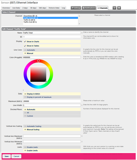
Example: Channel Settings for an SNMP Traffic Sensor
Select Channel |
|
Channel |
From the list, select the channel you want to change settings for. All settings below belong to the channel selected here. The content of the list depends on what channels are available for this sensor. The Downtime channel is different from other channels and not all setting options are available for it. Note: If you change the channel here then all unsaved settings below will be lost. |
Edit Channel "[Name]" |
|
Name |
Enter a meaningful name to identify the channel. The name will be shown in graphs and tables. You can automatically add the sensor's ID to the name by using the placeholder [#id]. |
ID |
The ID of the channel cannot be changed; it is used for unique definition. For example, you need the ID when using Sensor Factory sensors. |
Display |
Define where the channel will be displayed. Choose from:
To change this setting, remove or add the check mark symbol in front of it. |
Line Color |
Define in what color the channel shall be displayed in graphs. You can choose between
When you set this option to manual color definition please enter a color below. |
Color (#rrggbb) |
This option is only available if Manual is selected in the Line Color setting above. Please either enter a color in hexadecimal RGB notation (as in HTML/CSS), or choose a color from the visual color selector. The field containing the hexadecimal color value will change to the resulting color immediately in both cases. |
Data |
This setting is available for most channels. Define how data will be displayed. Choose between:
|
Maximum ([unit]) |
This field is only visible if the percent of maximum setting is selected above. Enter a value that will be regarded as maximum. Please pay attention to the given unit. All percent values will be calculated based on this value. Please enter an integer value. |
Line Width |
Define in what color the channel shall be displayed in graphs. Enter an integer value in pixels. Although the line width is not limited, we recommend using values between 1 and 7 only in order to achieve optimal results. |
Decimal Places |
Define how many decimal places of the channel's data shall be displayed in graphs and tables. You can choose between
|
Spike Filter |
A spike filter can be used to correct obviously faulty monitoring data. Sometimes, sensors report enormously high or far too low values; due to an error in data transmission, or due to incompatibilities of the physical device you are monitoring. This can make graphs unreadable. A spike filter can compensate for these flaws. When enabled values above and below a certain limit are disregarded in the monitoring data for graphs and tables. Note: The monitoring data itself will not be changed (but only the presentation of the data) and this setting is valid for all data of this channel (also the historic data). You can choose between
Note: The spike filter option is not available for the channel Downtime. |
Spike Filter Max. Value [unit] |
This field is only visible if spike filter is enabled above. Specify the maximum value allowed in the channel's data. All values above this value will be disregarded in graphs and tables. Please enter an integer value or leave the field empty. |
Spike Filter Min. Value [unit] |
This field is only visible if spike filter is enabled above. Specify the minimum value allowed in the channel's data. All values below this value will be disregarded in graphs and tables. Please enter an integer value or leave the field empty. |
Vertical Axis Scaling |
Define how the vertical axis for the channel is displayed in graphs. You can choose between
Note: Settings for this option are ignored if Chart Type Stack channels on top of each other or Show in and out traffic as positive and negative area chart (available for traffic sensors) is enabled in the sensor's Settings tab. |
Vertical Axis Maximum [unit] |
This field is only visible if vertical axis scaling is enabled above. Specify the maximum value that shall be used on the vertical axis for the channel. Enter an integer value. |
Vertical Axis Minimum [unit] |
This field is only visible if vertical axis scaling is enabled above. Specify the minimum value that shall be used on the vertical axis for the channel. Enter an integer value. |
Limits |
The channel can affect the status of the sensor it is part of. By entering limits, you can define when the sensor will enter a Warning or Down status; depending on the channel's data. Using this function, you can e.g. set a traffic sensor (which is usually never in a down state) to error when certain limits that you consider critical are reached. You can choose between
Note: The limits option is not available for the channel "Downtime". |
Upper Error Limit [unit] |
This field is only visible if limits are enabled above. Specify an upper limit for an error state. If the channel's values overrun this value, the sensor will be set to Down. Note: While in Down status, a sensor does not record any data in all of its channels. Please enter a decimal value or leave the field empty. |
Upper Warning Limit [unit] |
This field is only visible if limits are enabled above. Specify an upper limit for a warning state. If the channel's values overrun this value, the sensor will be set to Warning. Please enter a decimal value or leave the field empty. |
Lower Warning Limit [unit] |
This field is only visible if limits are enabled above. Specify a lower limit for a warning state. If the channel's values undercut this value, the sensor will be set to Warning. Please enter a decimal value or leave the field empty. |
Lower Error Limit [unit] |
This field is only visible if limits are enabled above. Specify a lower limit for an error state. If the channel's values undercut this value, the sensor will be set to Down. Note: While in Down status, a sensor does not record any data in all of its channels. Please enter a decimal value or leave the field empty. |
Error Limit Message |
This field is only visible if limits are enabled above. Enter an additional message. It will be added to the sensor's message when entering a Down status. Please enter a string or leave the field empty. |
Warning Limit Message |
This field is only visible if limits are enabled above. Enter an additional message. It will be added to the sensor's message when entering a Warning status. Please enter a string or leave the field empty. |
Click on Save to store your settings before you select another channel in the Select Channel section!
For information about sensor settings, please see the following sections:
- Sensor Settings
- List of Available Sensor Types
- Additional Sensor Types (Custom Sensors)
- Sensor Channels Settings
- Sensor Notifications Settings
Ajax Web Interface—Device and Sensor Setup—Topics
Other Ajax Web Interface Sections
Related Topics |
Keywords: Line,Line Color,Line Width,Decimal Places,Spike Filter,Peak Filter (Spike Filter),Vertical Axis Scaling,Limits,Limits Error,Limits Warning,Error Limit,Warning Limit,Configure,Configure Sensor Channel,Sensor,Sensor Channel Settings